
- #10 position dip switch calculator pdf
- #10 position dip switch calculator serial
- #10 position dip switch calculator driver
- #10 position dip switch calculator manual
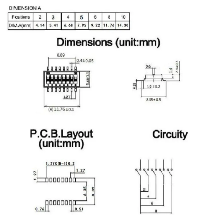
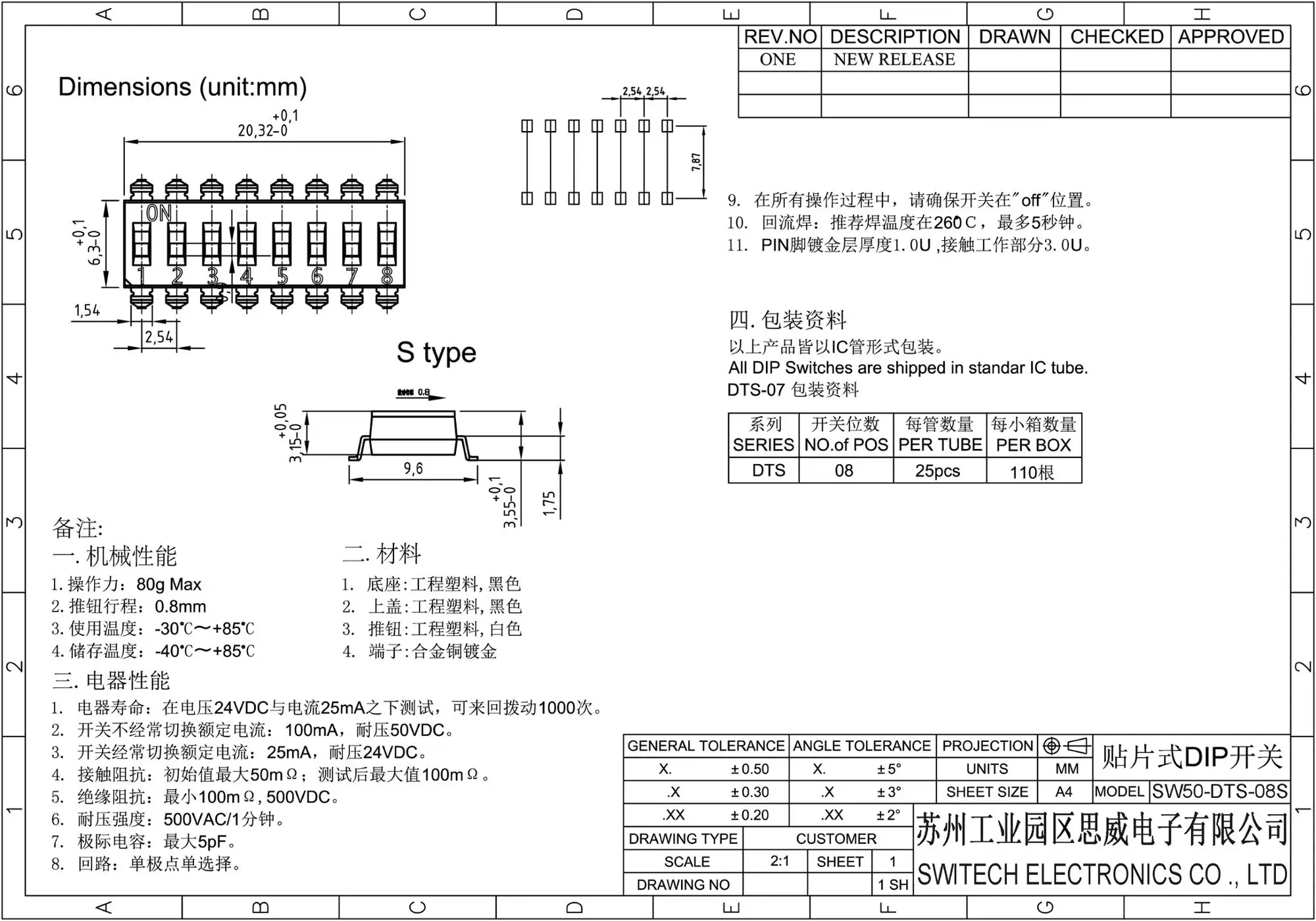
PDF 檔案11 Table 2: Communication port configuration (for 8-position DIP switch) NOTES: DIP switch position 6 on ‘ON’ position enables a 121Ω termination resistor to RS-485 two-wire configuration only (must be kept on ‘OFF’ position in any other configuration) DIP switch position 8 on ‘ON’ position enables a 121Ω termination resistor to.So a tri-state switch will connect the circuits to either position ‘A’ or position ‘B’, or neither, making it a 3-state switch. On the other side of the switch will be only 2 or 3 pins. The terminals are molded into the thermoset base and provide an electrostatic discharge shield rating toĭIP Switch Diagrams and DIP Switch stylesįor example an 8 position switch will have 8 pins, on one side of the body, for each of the different switch circuits. Raised slide switches with Gold plated contacts and 10,000 cycle switching life, 50mA 24VDC, SPST on/off. Set the remainingĨ Position PCB Mount DIP Switch (SW1003).
#10 position dip switch calculator driver
or If your video source is DVI (using an HDMI adapter), use the included screw driver to set Dip switch 6 to the ON position (up). If your video source is HDMI, use the included screw driver to set Dip switch 6 in the OFF position (down).

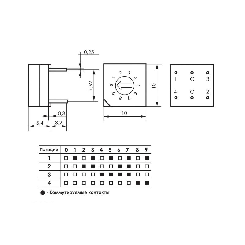
This type of switch is designed to be used on a printed circuit board along with other electronic components and is commonly used to customize the behavior of an electronic device for specific situations.ĮDID Emulator and Copier for HDMI Displays The term may refer to each individual switch, or to the unit as a whole.
#10 position dip switch calculator manual
16 Figure 17 – Default Jumper Settings on CoreSenseĪ DIP switch is a manual electric switch that is packaged with others in a group in a standard dual in-line package (DIP). 16 Figure 16 – 10 Position Jumper Settings on CoreSense Protection Modules Prior to 2015.
#10 position dip switch calculator serial
Setting the DIP switch (RS-232C Serial Interface) 2. When one of these formats is present and embedd ing is turned on, the PASS HANC DIP switch NOTE: 2048x1080p/psf 29.97 and 30 formats support a maxi mum of 8 channels of embedded audio.

Switch values are as follows: DIP Switch 2 Adjust the individual switches until their sum equals the device address. This should be a number between 1 and 254. Use DIP switch 2 to set the address of the device.


 0 kommentar(er)
